Uneven grooves ruin panels, slow assembly, and waste your day.
You feel the pain, you try compensation, and the problem still comes back.
Uneven grooves usually happen because the table is not flat enough, the tool is not installed perfectly, or the calibration/compensation is not matched to your real surface. Automatic depth compensation helps, but the best solution is mechanical: keep the table height error within 0.5 mm to make groove depth consistent.

I will be direct: if you keep chasing compensation settings while ignoring table flatness, you will stay in a loop.
If you want perfect grooves, keep reading, because I will show you the real root causes and the practical fix order.
Is the Real Problem Your “Compensation Setting”… or Your Table Flatness?
You tweak numbers, you rerun a test, and one side is still deeper.
You blame software, but the machine keeps telling the truth.
Your compensation is only as good as your reference surface. If your cutting table has mechanical high-low error, the tool meets the panel at different heights. A V-groove tool is sensitive to height change because it is cutting at an angle. That small height difference turns into a visible depth difference on the groove.
A good controller can do auto knife depth compensation, but it cannot fully cancel a table that is not mechanically stable. In real production, the best-performing shops do this first: they ensure the worktable flatness error is controlled within 0.5 mm across the effective working area. After that, compensation becomes a fine-tuning tool, not a rescue tool.

Why 0.5 mm Matters More Than Most Buyers Think
I like simple numbers, so let me show it in a visual way. When the table error gets bigger, the groove depth variation grows fast.
Flatness target vs typical groove depth risk (visual guide)
Table height error (mm)    Groove depth consistency risk
0.2 mm   ███               Low
0.5 mm   ██████            Controlled (recommended)
1.0 mm   ████████████      High (visible unevenness)
1.5 mm   ████████████████  Very high (scrap + rework)
This is why I always say: do compensation after the machine is mechanically correct.
Is Your Worktable Actually Flat Under Real Load and Vacuum?
The panel looks flat, but the groove says otherwise.
You measure once, you assume it is fine, then production proves it is not.
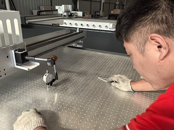
To judge flatness correctly, I never rely on “eye test.” I test flatness in the same condition as production: vacuum ON, underlay installed, and panel loaded. A table can look flat when empty, but it can change when vacuum zones pull, when the felt underlay has wear, or when the spoilboard has local compression.
What I Check First (In the Exact Order)
1) Flatness map across the full cutting area
I measure multiple points across X/Y. I do not measure only the center. I always include corners and zone boundaries.
2) Vacuum zone balance
If one zone pulls harder or leaks less, it can “bend” soft panels. That bend becomes groove depth change. A clean vacuum design with zoned control helps a lot.
3) Underlay condition (felt / spoilboard)
A worn underlay has local low spots. Those low spots create shallow grooves. If a corner has compressed felt, the groove depth changes there every time.
4) Gantry and toolhead perpendicularity basics
If the toolhead is not stable or the Z movement has play, the groove depth will drift across travel.

Quick Diagnostic Table I Use on the Shop Floor
| What you see on the panel | Most likely cause | What I do first |
|---|---|---|
| One side always deeper across all jobs | Table height error or gantry tilt | Measure flatness map, check rails, correct table |
| Depth changes near vacuum zone lines | Vacuum imbalance or underlay wear | Check zone sealing, replace underlay in that area |
| Start is deep, end is shallow (or opposite) | Z motion timing, accel/dec, compensation mismatch | Recalibrate Z, reduce speed for test, adjust compensation curve |
| Depth differs only on tight curves | Tool angle dynamics, speed too high | Slow down curves, check tool sharpness and tool offset |
This table saves time because it stops blind guessing.
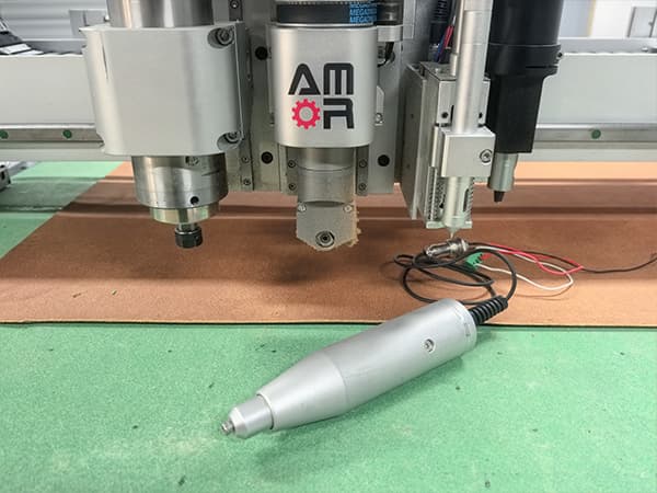
Is Your V-Groove Tool Installed Like a Precision Tool… or Like a “Good Enough” Tool?
A small installation mistake can look like a software problem.
You lose hours, and the real issue is one screw or one offset.
V-grooving for polyester acoustic panels is not forgiving. If the blade is not centered, if the tool is not aligned, or if the angle reference is inconsistent, your depth will change from left to right or start to end.
My Installation Rules That Prevent 80% of “Uneven Groove” Complaints
1) Blade centering and orientation must be consistent
I always install the blade so the tip is centered in the holder. I also keep the cutting edge direction consistent with the tool design. If the blade is slightly off, one side of the V can cut more aggressively.
2) Tool length and reference height must be measured, not guessed
If the tool length setting is off by even a small amount, the machine will “think” it is at the correct depth while the blade is actually higher or lower.
3) Angle setting must match the real groove process
For PET felt and polyester fiber panels, buyers often use 45°, 22.5°, 15°, or custom angles. If the angle is correct but the height reference is unstable, your depth will still vary.
4) Tool holder rigidity matters
A premium machine uses a rigid tool mount and stable Z axis. If the tool can micro-move under load, depth consistency disappears. This is why a strong machine structure is not a luxury. It is a quality requirement.

A Simple “Pass/Fail” Test I Run
I groove a straight line, then I groove the same line in reverse direction with the same program.
If the depth pattern changes, I know something is unstable in installation, tool offset, or mechanical rigidity.
Are You Calibrating Z-Depth the Right Way for Grooving, Not Just Cutting?
Your cutting depth looks fine, but your grooving depth is not stable.
That happens because grooving is more sensitive than cutting.
Many operators calibrate Z depth for cutting and assume grooving will follow. I do not do that. I treat grooving as its own process because the tool geometry amplifies small errors.
The Calibration Stack I Use (Practical, Not Theoretical)
Step 1) Z-axis repeatability check
I jog Z down to a reference surface, record the reading, lift Z, and repeat. If the repeatability is not stable, compensation cannot save you.
Step 2) Reference surface validation
I do not calibrate on a damaged underlay. I choose a clean reference area. If the reference area is soft or worn, I build error into the system.
Step 3) Multi-point depth verification
I groove test lines at multiple points across the table: left, center, right. I do not accept calibration if only the center looks good.
Step 4) Real material verification
I calibrate on the actual polyester acoustic panel. I do not calibrate on a different board. Different compression behavior changes the effective depth.
What “Good Calibration” Looks Like in Production
If the table height error is controlled within 0.5 mm, and the Z axis is repeatable, I can usually achieve groove depth consistency that is visually uniform across the sheet. After that, compensation becomes a small adjustment. It stops being a daily fight.
Are You Using Compensation as Fine Tuning, or as a Band-Aid?
You want one setting that fixes everything.
That setting does not exist if the table is not mechanically correct.
Automatic knife depth compensation is a great feature. I like it. I recommend it. But I treat it like a “stabilizer,” not like a miracle.
What Compensation Can Do Well
- It can correct small surface changes across the table.
- It can help when you switch from one underlay to another.
- It can reduce minor depth drift from wear over time.
What Compensation Cannot Do Reliably
- It cannot fully defeat a table with big mechanical high-low error.
- It cannot fix poor tool installation or unstable tool mounts.
- It cannot fix vacuum pull distortion caused by wrong zone use.
My “Best Practice” Compensation Workflow
1) Fix mechanics first (flatness ≤ 0.5 mm)
I always start here because it has the highest ROI.
2) Run a simple depth mapping routine
I map depth across key points, then I apply a small compensation profile.
3) Lock the process settings
Once stable, I avoid frequent changes. Frequent changes create new variables and new mistakes.

Why Premium Machines Win Here
A high-quality oscillating knife cutting machine usually has a stronger welded bed, better rail alignment, cleaner wiring, and a more stable Z-axis structure. Those are not marketing words. They are the foundation that lets compensation work as intended. If the structure is weak, compensation becomes a never-ending adjustment game.
Conclusion
Perfect grooves start with mechanical flatness ≤ 0.5 mm, then tool installation, then calibration, then compensation.